Outer Gunwhale Lamination
The outer gunwhale lamination is triangular: 15 mm wide at the base, 1 mm at the top and 25 mm high. It is made of Western Red Cedar. Detailed dimensions at each station can be found in the GUNWHALE / RUBBING STRAKE CONSTRUCTION drawing provided by designer Keith Callaghan.

To fit the outer lamination over the middle lamination, I used small wood screws to hold them together while bonding.
Once dry, I removed the screws. The angle and curvature of plank #8 makes it almost impossible to clamp the outer lamination securely over the middle lamination.

First, I held the outer lamination flush (at the bottom) against the middle lamination. Then I used a small drill bit to drill a screw pilot hole every 18 inches and avoid splitting the stock. For bonding, I applied West System epoxy resin with Colloidal Silica to both surfaces. Then I hand-tightened the screws. One at a time.


The rubbing strake is set at a constant 30 degrees to the vertical. This mean the outer lamination is set at a constant 60 degrees to the horizontal. To help me achieve the proper angle while shaving the stock with the block plane, I cut a simple plywood jig on the band saw.
 The angle at this point is (provided the lamination is cut per specification) from the bottom outer edge of the lamination to 1 mm off the opposite edge on the top. I shaved the outer lamination using the jig to gauge the proper angle and to verify it is flat so that the rubbing strake will have a flat surface to adhere to.
I made a lot of wood shavings in the process. This can be improved by cutting the outer triangular lamination on a precision table saw, thus eliminating the need to shave the angle.
Final Priming Of The Hull
 Once I finished fitting the outer lamination, I proceeded to sand and fill the bottom of the gunwhales, and finished priming the outside of the hull with two coats of Interlux two-part PrimeKote. I had to do a little bit of fairing too so I used Interlux Watertite two-part fairing compound over the Interlux PrimeKote, and later applied two coats of primer over the fairing compound, as instructed by Interlux.
 Port side view of the hull after priming.
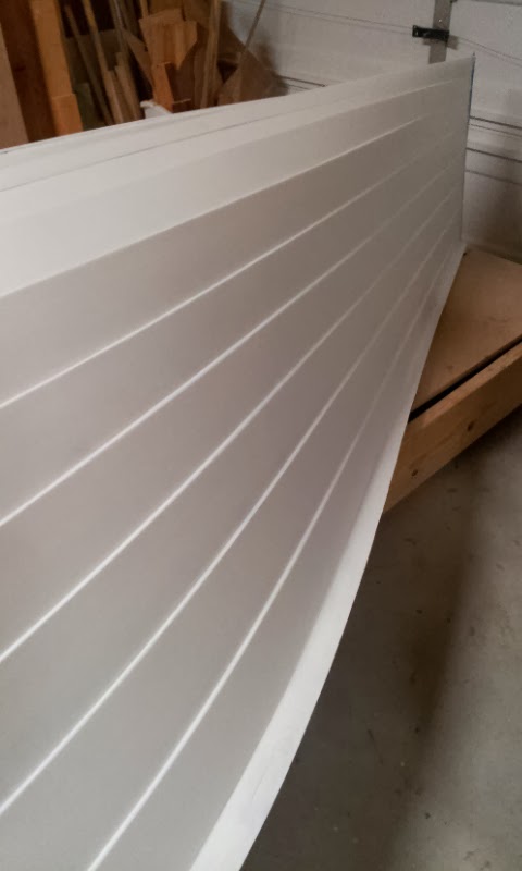
From the shrouds towards the bow, the gunwhale gradually reduces in width and depth. Detailed dimensions at each station can be found in the GUNWHALE / RUBBING STRAKE CONSTRUCTION drawing provided by designer Keith Callaghan.
View from the bow towards the transom

The Bow

Mid-Section

The Transom

Shaping The Centerboard Foil
In August, I bonded Western Red Cedar strips for the centerboard and the rudder, and I also cut both profiles using the drawings provided by Keith Callaghan. While the primer on the hull cures, I've decided to tackle the shaping of the centerboard and the rudder.
 It had been a while since I last studied the NACA foils table and drawings that Keith sent me, so I spent time revisiting and researching all of this information. Looking at the stations and ordinates table can be intimidating at first. What does it all mean?
I won't attempt to explain all of this (there is plenty of material in books and on the Internet) but I'd like to share a reference I found on "How To Loft Airfoil Sections" on page 6 in a PDF document called: How to Build Rudder Blades and Centerboards by the Gougeon Brothers. I hope the reference proves useful to you as it did to me.
 The centerboard reaches maximum thickness at 40% of the chord's leading edge. I made a pencil mark along that line on both sides of the centerboard.
 Next, I plotted the stations and ordinates on a piece of cardboard and cut a simple jig to gauge the rough shape of the centerboard while shaving it.
 I mounted the centerboard on my very old WorkMate work bench and sanded the edges to achieve a smooth profile.
 The block plane proved very useful for shaping the leading edge of the centerboard. For shaping the rest of the foil, however, i thought my hand power planer would do a more precise, consistent and faster job. I believe it did and I'm glad I used it. Plus I no longer have to justify owning one. Check!
Using the foil jig as reference, I continued to shave away with the hand power planer as needed until the X,Y shape was achieved.

Here is the centerboard shape I've achieved so far. These initial steps have shaped the centerboard only in two dimensions.
Next steps include shaping the centerboard to its 3rd dimension. More to come next month when I do this.
Shaping The Rudder Foil
To shape the rudder foil, I followed the same steps as with the centerboard. The rudder reaches maximum thickness at 30% of the chord's leading edge. I made a pencil mark along that line on both sides of the rudder.
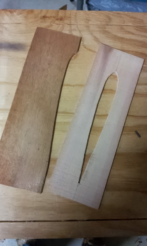 Next, I plotted the stations and ordinates on a thin piece of Western Red Cedar and cut a simple jig to gauge the rough shape of the rudder while shaving it.
I mounted the rudder on my WorkMate work bench and sanded the edges to achieve a smooth profile.

Again, the block plane proved very useful for shaping the leading edge of the rudder foil and the hand power plan for shaping the rest.
Using the foil jig as reference, I continued to shave away with the hand power planer as needed until the X,Y shape was achieved.


Here is the centerboard shape I've achieved so far. These initial steps have shaped the centerboard only in two dimensions.
Next steps include shaping the centerboard to its 3rd dimension. More to come next month when I do this.
Happy Holidays!
Happy Holidays!
No comments:
Post a Comment