Planking is Done!
Summer arrived to Austin with vengeance this year, with high temperature from the upper 90s (°F) / 30s (°C) to the low 100s (°F) / 40s (°C). August promises to be hotter.
Starting early in the morning (~5 am) on weekends, and late in the evenings during week days, allowed me to make progress while avoiding the highest temperatures. Always testing the fit before bonding and only mixing small batches of epoxy with West System's 209 Super Slow hardener and colloidal silica.
 Plank #4 was fitted relatively easy since no beveling was required on plank #3 landing except forward of 550 mm where each pair of overlapping planks is progressively bevelled together, so that at the stem there is no plank overlap. (Rule 4.m.(i)) ."
 An view of plank #4 towards the transom. Once again, while clamping the planks I noticed the torque exerted by the deep throat clamps. To counter this effect, I drilled holes in the building frames to clamp down the new plank against it and ensure the plank laid flat over the building frame landing.
A view of the hull from the transom with planks #4 installed.

A view of the hull from the bow with planks #4 installed
After bonding the planks I always remove the excess epoxy. Not only on the outside of the hull but also on the inside. This assures less sanding and fairing later on. I use the excess epoxy to fillet the joints or to fair parts of the hull.
 Looking at the bow from underneath the building frames. I'll have to use my rotary tool to smooth out the excess epoxy after filleting the joints. It was a tight place to work in but with the help of a brush I was able to put the excess epoxy to good use.

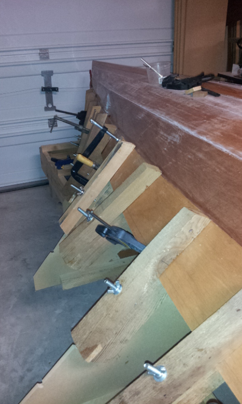
Looking forward at Station #2 from underneath the building frames. Notice the holes drilled in station #2 to clamp down planks #1 and #2.

Looking back at Station #3 from underneath the building frames. One can barely see the location where the king posts rest on the top middle section of the photo. Notice the black PVC tape used to avoid bonding between the building frame and the plank.
 Looking forward at Station #3 from underneath the building frames. Notice the opening of the centerboard case and its frame.
 Looking forward at Station #4 from underneath the building frames. Notice the wider opening of the building frame to allow for the lateral support "ears".
 Plank #5 on the starboard side. The planks now easily fit over the constructions frames and land on the previous plank without beveling, except forward of 550 mm as discussed earlier.
Plank #5 on the port side. The planks now easily fit over the constructions frames and land on the previous plank without beveling, except forward of 550 mm as discussed earlier.
 To clamp down port side #5 plank at the bow. I had to use adjustable clamps on each plank first and then clamp them together to tighten them up against the apron. As you can see, there are a number of clamp types laying around that I tried first but didn't achieve the proper grip.
  A view from the bow after bonding planks #5.
 An aft view of plank #6, port side
Forward view of plank #6, port side. One can barely see the perfect pencil mark alignment over station #2 in the middle of the picture.

A view from the bow after bonding planks #6. I marked the location of the top and bottom edges of each plank on the apron. This was very helpful in aligning the planks and achieving symmetry.
 Plank #7 on the starboard side.
 Forward view of plank #7 on the port side.
 Aft view of plank #7 on the port side.
A view from the bow after bonding planks #7. It was exciting to see the progress day after day and discover the new hull lines.
 And finally, plank #8 on the starboard side. Clamping down both ends of the plank required some creative setups and different clamp types. At the transom, I used a small "C" clamp to hold the end tight against the landing on the previous plank and a bar clamp hooked under the jig to hold the plank against the transom. A deep throat clamp holds the plank tight against the landing.
 For clamping down plank #8 against the building frame, I cut off a small triangle from the building frame to provide a parallel surface to clamp from. This was done with a reciprocating saw.
A forward view of plank #8 at the bow end, on the port side. I used a small block of wood to secure the plank against the apron.
 A view from the bow after bonding planks #8. I used a coping saw first and then the block plane to remove the excess material at the bow.
 Then I sanded and faired the planks at the stem so there are no plank overlaps
Trimming the planks around the transom
After all planks were fitted, I used a router with a trimming bit to remove the excess plank material at the transom. The trimming bit worked perfectly since its wheel bearing guide leaves less than 1 mm of material that I plan to remove when I sand the transom with my orbital sander.


The Bilge Keels
For the bilge keels I used solid oak stock I had left from a previous project and cut 2 pieces about 1200 mm long x 45 mm wide x 12 mm thick. The bilge keels are made and fitted per Merlin Rocket Class Rules 4(l)(ii). Designer Keith Callaghan recommends fitting the bilge keels soon after planks #2 are fitted. Construction Note #15 recommends fitting the bilge keels for sure before the hull is taken off the building frames. I regret no having fitted the bilge keels soon after planks #2 were fitted and use the deep throat clamps to hold them down during bonding. This would've been really easy. Instead, I fitted the bilge keels later and had to resort to some very interesting ceiling bracing and clamping to hold them in place. Like trying to catch a fish with you bare hands.


Looking aft at the bilge keels after being fitted. The edges are rounded and the ends are tapered to a rounded tip.
 The Hazardous Zero 9 Bow Profile drawing specifies for a "FALSE STEM made from 25 mm thick hardwood. This is added after the hull has been planked up." To do this, I planed a 600 mm long x 120 mm wide piece of hardwood to the require thickness. Then, I traced the shape of the bow cross section on the hardwood.
For cutting the stem, I used a band saw rather than a jig saw. The band saw made a very smooth cut. It was easy to feed and turn the stock to follow the curved profile of the stem.
 Holding the stem against the apron was somewhat of a challenge. At the keel, I rigged a hardwood stock coming out of the centerboard slot, from which I hooked a bungee cord to a turnbuckle, from which I hooked another bungee cord looped to the stem.
At the sheer line, two clamps held the stem tight against the apron during bonding.
And finally, after much shaving and sanding, the stem is starting to look really nice. More fun ahead as this Merlin Rocket gets built!
