Saturday, November 30, 2013

November, 2013

Outer Gunwhale Lamination

The outer gunwhale lamination is triangular: 15 mm wide at the base, 1 mm at the top and 25 mm high. It is made of Western Red Cedar. Detailed dimensions at each station can be found in the GUNWHALE / RUBBING STRAKE CONSTRUCTION drawing provided by designer Keith Callaghan.


To fit the outer lamination over the middle lamination, I used small wood screws to hold them together while bonding.

Once dry, I removed the screws. The angle and curvature of plank #8 makes it almost impossible to clamp the outer lamination securely over the middle lamination.


First, I held the outer lamination flush (at the bottom) against the middle lamination. Then I used a small drill bit to drill a screw pilot hole every 18 inches  and avoid splitting the stock. For bonding, I applied West System epoxy resin with Colloidal Silica to both surfaces.  Then I hand-tightened the screws. One at a time.


Port side view towards the transom.


The rubbing strake is set at a constant 30 degrees to the vertical. This mean the outer lamination is set at a constant 60 degrees to the horizontal. To help me achieve the proper angle while shaving the stock with the block plane, I cut a simple plywood jig on the band saw.


The angle at this point is (provided the lamination is cut per specification) from the bottom outer edge of the lamination to 1 mm off the opposite edge on the top. I shaved the outer lamination using the jig to gauge the proper angle and to verify it is flat so that the rubbing strake will have a flat surface to adhere to.

I made a lot of wood shavings in the process. This can be improved by cutting the outer triangular lamination on a precision table saw, thus eliminating the need to shave the angle.


Final Priming Of The Hull

Once I finished fitting the outer lamination, I proceeded to sand and fill the bottom of the gunwhales, and finished priming the outside of the hull with two coats of Interlux two-part PrimeKote. I had to do a little bit of fairing too so I used Interlux Watertite two-part fairing compound over the Interlux PrimeKote, and later applied two coats of primer over the fairing compound, as instructed by Interlux.

Port side view of the hull after priming.
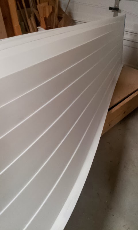
From the shrouds towards the bow, the gunwhale gradually reduces in width and depth. Detailed dimensions at each station can be found in the GUNWHALE / RUBBING STRAKE CONSTRUCTION drawing provided by designer Keith Callaghan.


View from the bow towards the transom

The Bow

Mid-Section

The Transom


Shaping The Centerboard Foil

In August, I bonded Western Red Cedar strips for the centerboard and the rudder, and I also cut both profiles using the drawings provided by Keith Callaghan. While the primer on the hull cures, I've decided to tackle the shaping of the centerboard and the rudder.

It had been a while since I last studied the NACA foils table and drawings that Keith sent me, so I spent time revisiting and researching all of this information. Looking at the stations and ordinates table can be intimidating at first. What does it all mean?

I won't attempt to explain all of this (there is plenty of material in books and on the Internet) but I'd like to share a reference I found on "How To Loft Airfoil Sections" on page 6 in a PDF document called: How to Build Rudder Blades and Centerboards by the Gougeon Brothers. I hope the reference proves useful to you as it did to me.

The centerboard reaches maximum thickness at 40% of the chord's leading edge. I made a pencil mark along that line on both sides of the centerboard.

Next, I plotted the stations and ordinates on a piece of cardboard and cut a simple jig to gauge the rough shape of the centerboard while shaving it.

I mounted the centerboard on my very old WorkMate work bench and sanded the edges to achieve a smooth profile.
The block plane proved very useful for shaping the leading edge of the centerboard. For shaping the rest of the foil, however, i thought my hand power planer would do a more precise, consistent and faster job. I believe it did and I'm glad I used it. Plus I no longer have to justify owning one. Check!

Using the foil jig as reference, I continued to shave away with the hand power planer as needed until the X,Y shape was achieved.


Here is the centerboard shape I've achieved so far. These initial steps have shaped the centerboard only in two dimensions.

Next steps include shaping the centerboard to its 3rd dimension. More to come next month when I do this.


Shaping The Rudder Foil

To shape the rudder foil, I followed the same steps as with the centerboard. The rudder reaches maximum thickness at 30% of the chord's leading edge. I made a pencil mark along that line on both sides of the rudder.
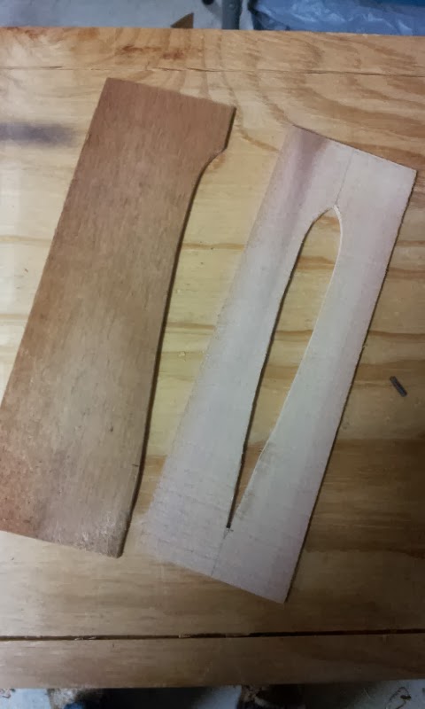
Next, I plotted the stations and ordinates on a thin piece of Western Red Cedar and cut a simple jig to gauge the rough shape of the rudder while shaving it.

I mounted the rudder on my WorkMate work bench and sanded the edges to achieve a smooth profile.


Again, the block plane proved very useful for shaping the leading edge of the rudder foil and the hand power plan for shaping the rest.


Using the foil jig as reference, I continued to shave away with the hand power planer as needed until the X,Y shape was achieved.


Here is the centerboard shape I've achieved so far. These initial steps have shaped the centerboard only in two dimensions.

Next steps include shaping the centerboard to its 3rd dimension. More to come next month when I do this.


Happy Holidays!


Friday, November 1, 2013

October, 2013

The Bow Tank Top Reinforcements

The Merlin Rocket Owners Association website has a great reference library and photographs on boat repair, renovation and self build. I do a bit of research in the site, looking for tips and advise.

In one of those libraries I found an interesting photograph. I wondered, what would happen if I had to go under the deck to do upgrades, maintenance or repairs? The bow tank top would fail and collapse under my weight. It is made of 4 mm thick marine plywood supported by the bulkhead, the bow tank beam and top of plank land #4.

I decided to add Red Western Cedar strips next to the top of plank land #4 and a center beam from the bulkhead to the stem. Additionally, I added two vertical supports from the hog to the  beam.


The Shroud Knee


There are 2 shroud knees made of 12 mm marine plywood, half-lapped on to the bow tank bulkheads. I secured the starboard shroud knee to the bow tank bulkhead with a clamp and used an angle finder to determine the bevel angle between the shroud knee and the planks. Notice I position the angle finder perpendicular to the shroud knee and not in parallel with the plank.


I then positioned my angle finder against the band saw miter fence and read the angle on the scale. This step can avoided by using an angle finder with a built in scale.
Then, I set the band saw table at the same angle and proceeded to cut along the edge of the shroud knee. Before cutting, I made sure to mark the area to be removed. Given that my band saw table only inclines to one side, I started the cut on the port side shroud knee from the opposite side.

Before bonding the shroud knee I set it in place and clamped it on both ends. Then, I inspected the fit for gaps.


Looking at the shroud knee fit from the other side... not bad.


Another view of the starboard shroud knee.

A photograph of the shroud knees from the transom. I laid the bow tank tops to ensure the fit was right.


Filleting, Sanding & Epoxying

All these fittings inevitably come with their fair share of bonding and filleting, followed by painstaking sanding, sanding and more sanding. Afterwards, I coated the inside of the hull with epoxy. A couple of times over the fiberglass reinforcements until smooth.


A view from the bow.

Another view from the bow, this one up a bit higher.


Middle Gunwhale Lamination

The middle gunwhale lamination is 15mm wide x 25mm tall, and made of Western Red Cedar. It tapers out between station #1 & #2. Detailed dimensions at each station can be found in the GUNWHALE / RUBBING STRAKE CONSTRUCTION drawing provided by designer Keith Callaghan.


To fit the middle lamination over the inner lamination, I had to use small wood screws to hold them together while bonding. Once dry, I removed the screws. The angle and curvature of plank #8 makes it almost impossible to clamp the middle lamination securely over the inner lamination. 


First, I held the middle lamination flush (at the bottom) against the inner lamination. Then I used a small drill bit to drill a screw pilot hole every 18 inches  and avoid splitting the stock. For bonding, I applied West System epoxy resin with Colloidal Silica to both surfaces.  Then I hand-tightened the screw. One at a time.                                                                                                                                                                                                                                       

Starboard view of the middle lamination.


Port side view towards the bow.


Port side view towards the transom.

Monday, September 30, 2013

September, 2013

Interior Construction

Getting started on the interior construction required sanding the plank joints, around the apron, the transom, the hog and the centerboard. Prior to fitting the planks I used an orbital sander on them so the surfaces were fairly smooth for the most part.

Even though I'll have to sand again once filleting is done and fiberglass reinforcements are fitted, it is worth the effort and it will be noticeable after applying paint or varnish.


The Main Spaceframe

Prior to fitting the Main Space Frame, I placed a rope across the hull and tightened it until the dimensions between the top of planks' #8 were precisely as indicated in the layout drawing.


I then placed a square against the centerboard case and the Main Space Frame. Once squared to the garboard, I marked the final location of the port side Main Space Frame. A good mix of epoxy resin with colloidal silica was then applied for bonding.

The starboard side Main Space Frame went through the same process,

The Centerboard Side Stiffeners


It is recommended that the side stiffeners be fitted prior to mounting the centerboard case over the hog. The openings on the construction frames allow plenty of room to insert the centerboard case in place.


Fitting the centerboard through the construction frames was easy. I regret not having fit the side stiffeners earlier. Clamping and handling at this point was a bit awkward. There is much better access to the centerboard when it is on the workbench or soon after being fitted to the hog.


Centerboard Bolt Reinforcements

Once the centerboard side reinforcements were bonded, I fitted the bolt reinforcements. I placed a long drill bit through the hole for alignment with the starboard side bolt reinforcement. With a small square against the drill bit and the reinforcement, I ensured the alignment reference was perpendicular to the centerboard case.


After marking the proper location of both reinforcements and verifying there were no gaps with the hog or the side reinforcements, a mix of epoxy resin with colloidal silica was applied for bonding.


This month my photographs are a bit out of sequence. I didn't take them after each step as I usually do, so I had to go back and take them after I had taken a couple more steps. Notice the filleting beads I applied throughout.


Aft Spaceframe

The aft spaceframe drawing provided by designer Keith Callaghan specifies "2 halves of spaceframe are scarf joined at the centreline (6:1 scarf joint)."

Prior to fitting the Aft Space Frame, I placed a rope across the hull and tightened it until the dimensions between the top of planks' #8 were precisely as indicated in the layout drawing. It is important that no gaps exist between the spaceframe and the hull.


So I dusted off the router jig I built to scarf the planks and proceeded to scarfed the two spaceframe halves. Prior to scarfing I placed both halves in place and marked the overlap on both pieces.


Once again, the result was a sharp and smooth cut. 


Now that looks like a nice scarf joint...


Wait! What? Oh, gee!  You may remember my jig had an 8:1 slope. The drawing calls for a 6:1 slope.... Oops!  Fortunately, the difference is not much and I was able to fill the gap when I was filleting. 

I marked the ends on both sides and the direction of the cut on each aft spaceframe half to avoid a wasteful outcome. Then, I applied clear epoxy first on the exposed plywood and about 5 minutes later I applied an epoxy and colloidal silica bonding mix to the scarf joint. Clamping on a temporary work bench was easy.


Once bonded and sure that no gaps between the aft spaceframe and the hull existed, I fitted the aft spaceframe to the hull with a bonding mix of West Marine 105 epoxy and 406 colloidal silica.


The Main Bulkhead & Bow Tank Beam

The Main Bulkhead drawing provided by designer Keith Callaghan gives a great deal of detail: "The bulkhead is made from 6mm plywood and is angled at 62 degrees to the centreline."


I also beveled and fitted the bow tank beam and added reinforcements of Western Red Cedar to support the bow tank top.

Another specification reads: "aft face is 1738 aft at bevelled surface of land #4". Beveling is a variable 3-dimensional task at each plank. Fun times indeed!
Painstakingly, I took the time to plan, prep and execute these tasks to achieve the desirable result. Beveling is important to achieve a close fit. Supporting the bulkheads at the right angle for bonding requires some time and preparation. I used a combination of Western Red Cedar blocks and temporary duct tape. The bow tank tops provide a great reference when placing the bulkhead on the hull and marking its final location. A lot of sanding before starting was required and a lot more will be required later.


Reinforcement Of Lands Between Planks #2 & #3

The land between planks 2 and 3 has only about 16 mm of bevelled land to glue to. There is a sharp turn there and I'm concerned that, if I fall (and I most likely will... several times), the epoxy will hold but the plywood may give up.

Therefore, and based on Keith's recommendation, I placed an epoxy fillet along this land, internally, from the bow tank to the aft space frame, then I applied one layer of 75 mm wide glass tape and one layer of 50 mm wide glass tape. This should beef it up sufficiently for me.


Keith Callaghan's Construction Note #8 specifies: "Each plank overlaps the next plank nearer the garboard plank on the outside. The plans show a nominal overlap of 19 mm, but where planks overlap at an angle greater than about 15 degrees (as in the bow sections near the waterline), the bevelling of the land causes this overlap to be reduced. In the bows, local reinforcement is desirable in these areas (eg glass reinforcement internally)."

And so I've reinforced the hull from bow to stern.


A view of the reinforcements between the transom and the aft spaceframe.


A view of the reinforcements from the bulkheads to the aft spaceframe.

And here she is now...

Now, where is my orbital sander and dust mask? The fun continues...